43 wiring diagram on a trailer
November 7, 2019 - Jun 27, 2017 - 7 pin trailer plug light wiring diagram color code R and P Carriages is a Trailer dealership located in Seneca, IL. We carry the latest Kwik Load Trailers, Sure-Trac and Pace American models, including Utility, Dump and Cargo Trailers. We also offer rentals, service, and financing near the areas of Chicago, Seneca, Ottawa, Dekalb and Joliet.
Apr 8, 2019 - Explore Johnny J.'s board "Trailer Wiring Diagram" on Pinterest. See more ideas about trailer wiring diagram, trailer, trailer light wiring.
Wiring diagram on a trailer
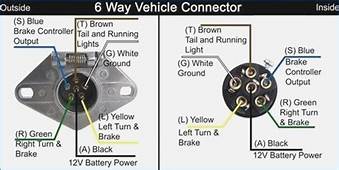
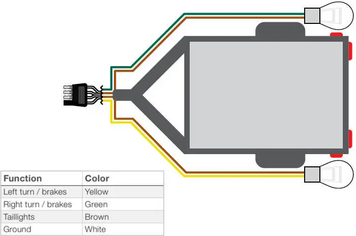
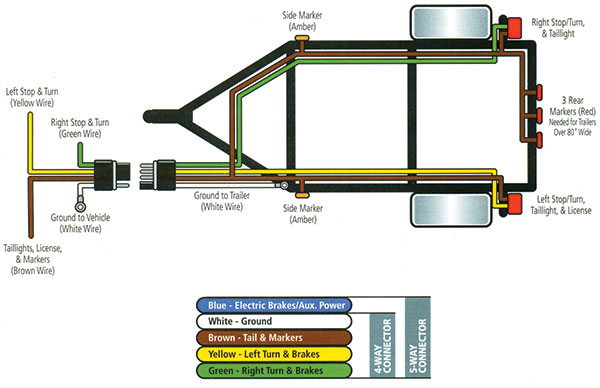
6-Pin Trailer Wiring Diagram. White Pin to your ground. Attach WHITE ground wire to vehicle frame. 34 inch by 1 inch 6 way rectangle connectors right turn signal green left turn signal yellow taillight brown ground white. 1 Check all small wires and make sure they are connected to the small fluid control solenoids. Trailer Wiring Diagrams 4 Way Systems. 4 way flat molded connectors allow basic hookup for three lighting functions; right turn signal / stop light (green), left turn signal / stop light (yellow), taillight / license / side marker (brown) and a ground (white). Complete with a color coded trailer wiring diagram for each plug type, including a 7 pin trailer wiring diagram, this guide walks through various trailer wiring installation solution, including custom wiring, splice-in wiring and replacement wiring. If your vehicle is not equipped with a working trailer wiring harness, there are a number of different solutions to provide the perfect fit for ...
Wiring diagram on a trailer. With our wide selection of enclosed, dump, equipment, car hauler, and utility trailers, H&H Trailers can help you find the perfect trailer for your needs. Check us out. Wiring Diagram Trailer Plugs and Sockets. Narva 7 and 12 pin trailer connectors comply with all relevant ADRs. Flat connectors comply with Australian Standards AS4177.5-2004. Large and small round connectors comply with AS2513-1982 while Heavy duty connectors meet the AS4735-2003 standard as required for vehicles and trailers over 3.5 tonnes. Assortment of jayco trailer wiring diagram. A wiring diagram is a simplified traditional pictorial representation of an electrical circuit. It reveals the components of the circuit as streamlined shapes, as well as the power and also signal connections between the devices. small 6 pin round plug & socket · 1 tail, clearance - brown
Great Dane Trailers Wiring Diagram Semi Trailer Car Freight Transport Electrical Wires Cable Png Pngegg. Gravely 994602 000101 Surfer Gsrka1952s Parts Diagram For Wiring Harness. I Have A 2011 Great Dane Trailer With Wabco Abs Module And The Fault Code Sid 4 Fmi 5 Already Replaced. Great Dane Trailers Wiring Diagram Semi Trailer Flatbed Truck ... It’s very confusing how all the plug diagrams are from the cable side, not as you look at them end on. I’m guessing someone wired the trailer (or car) the opposite way around. Melting sounds more like a short to me though. I’m sure the sparky can sort it out for you. November 20, 2021 · Wiring Diagram. by Trafalgar D. Law. Jvc Kw-X840bts Wiring Schematic - Wiring Diagram is the visual representation of a complicated electrical circuit. It stands for the physical parts of the electric circuit as geometrical shapes, with the real power and also connection links between them as slim edges. It is really…. Trailer Wiring Diagrams One of the most important parts of fitting a towbar to your vehicle is connecting the electrics from the towing vehicle to the trailer or caravan that you are towing. The electrics are required to power the lights on your trailer and, if you own a caravan, the internal electrics inside the caravan, therefore it is ...
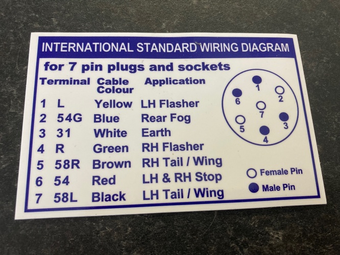
This contact has chosen to use one of the connections of the ISO 1724 is used for position light to electric brakes (Pin 5, 58R), which means that if you connect a trailer with electric brakes to a towing vehicle wired according to ISO 1724 and turn on the position lights the trailer will be ... 7 Pin Trailer Wiring Diagram. A wiring diagram is an ordinary photographic representation of a complicated electrical circuit. This kind of diagramming is generally made in a variety of layouts, including electrical diagrams, WIFI-style diagrams, power supply diagrams, and also wiring table diagrams. The most typical as well as very easy to ... Semi Trailer Wiring Diagram 7 Way wiring diagram is a simplified satisfactory pictorial representation of an electrical circuit. Two 3 axle semi-trailers an A or lead trailer and a B or second trailer. Trailer set-ups Axle Weight Axle Weight Axle Weight 12000 Ibs 34000 Ibs 34000 Ibs 80000 Ibs 40ft. The below information is for reference and is ... April 3, 2019 - A faulty and unsecured ground wire is often the issue of electric problems on a trailer. So study the chart and diagrams below to see how you can wire your trailer. If you need more information we are happy to help, Click here to contact us. Here is a great article on How To Wire A Trailer.
Trailer Wiring Diagram For 4 Way 5 Way 6 Way And 7 Way Circuits
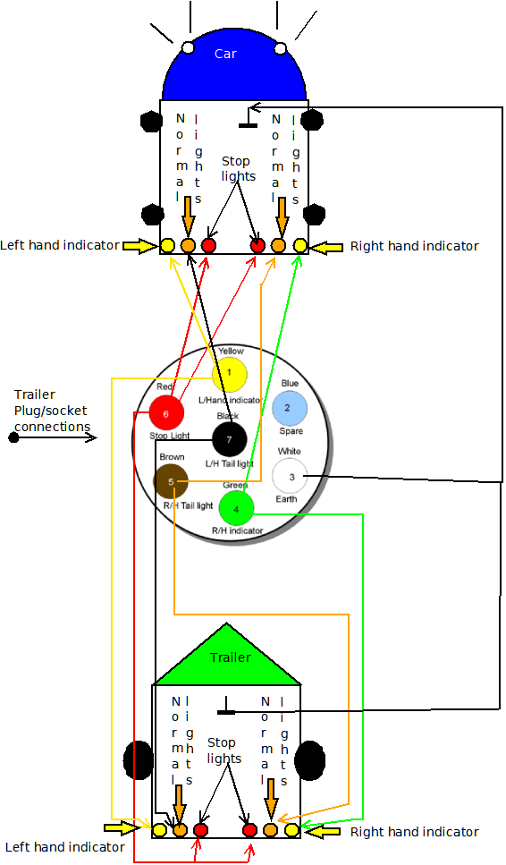
12N (normal) electrics wiring diagram for the exterior lighting on a trailer or caravan from Western Towing.
Trailer Wiring Diagrams North Texas Trailers Fort Worth
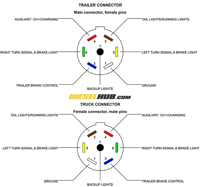
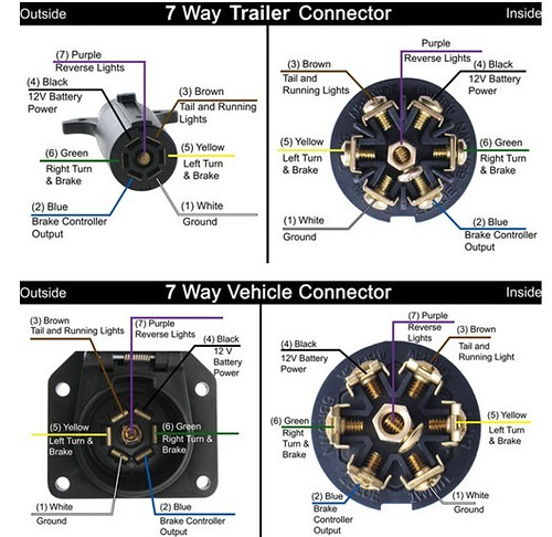
We have an excellent wiring diagram on our website, I will provide you a link so you can look at it. If you are looking at the inside of the trailer connector where the wires mount to the terminals starting at the top and rotating clockwise: 1:00 is Black and 12 volt power. 3:00 is Green and Right Turn and Brake. 5:00 is Blue and Brake Controller.
Trailer Connector Pinout Diagrams 4 6 7 Pin Connectors
Trailer Wiring Diagram. Boat trailer color wiring diagram. Use this as a reference when working on your boat trailer wiring. Includes 5 and 7 wire plug and trailer wiring schematics. Branson Werner. When not working his heart out on websites, e-commerce, and programming, Branson like to enjoy time on the lake.

Towbar Information Towbar Electrics Wiring Diagrams Malcolms Towbars Dublin Ireland
Check out or trailer wiring diagrams for a quick reference on trailer wiring. The below information is for reference and is commonly used throughout the industry, but can vary depending on who built the trailer. You can use a circuit tester to verify connections. Trailer Connectors.

Wiring Diagrams Towing Centres Uk Ltd
Pole Travel Trailer Connector Wiring Color Code. Wiring Diagram For Trailers Caravans. Trailer Circuit Wiring. Pin S Type Caravan Wiring Uk Trailer Parts.
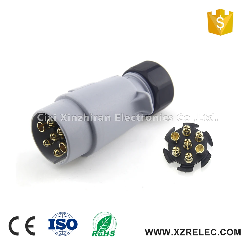
7 Pin Small Round Plastic Wiring Diagram Trailer Plug Buy Trailer Plug Wiring Diagram Trailer Plug Plastic Wiring Diagram Trailer Plug Product On Alibaba Com
Trailer Wiring Diagrams Trailer Wiring Connectors Various connectors are available from four to seven pins that allow for the transfer of power for the lighting as well as auxiliary functions such as an electric trailer brake controller, backup lights, or a 12V power supply for a winch or interior
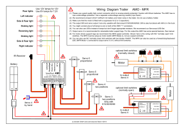
Wiring Diagram Trailer Amo Mfr Manualzz
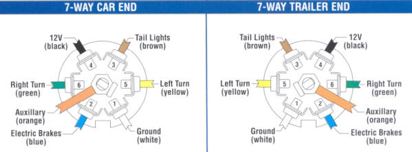
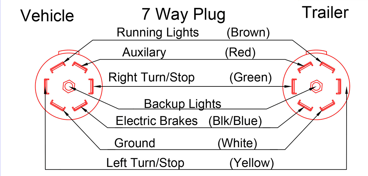
7 Way Plug Wiring Diagram Standard Wiring* Post Purpose Wire Color TM Park Light Green (+) Battery Feed Black RT Right Turn/Brake Light Brown LT Left Turn/Brake Light Red S Trailer Electric Brakes Blue GD Ground White A Accessory Yellow This is the most common (Standard) wiring scheme for RV Plugs and the one used by major auto manufacturers today.

Trailer Wiring Diagrams North Texas Trailers Fort Worth
Wiring Diagram Of 7 Pin Trailer Plug - People today understand that trailer is a car comprised of quite complicated mechanics. This vehicle is designed not just to travel one place to another but also to carry heavy loads.
Trailer Light Wiring Diagram
This is a basic reference article about trailer and caravan wiring; the plugs and sockets that are commonly in use in Australia, and the pin colour codes that are designed to coordinate proper connections, according to Australian Standards.

Wiring Diagrams C B Quality Trailer Works Inc
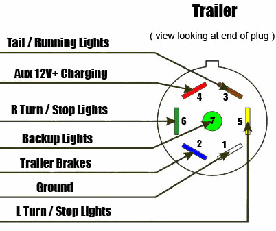
The 7-Way Trailer Plug is around 2″ diameter connector that allows an additional pin for an auxiliary 12-volt power or backup lights. It is usually used for towing heavy-duty cargo trailers, aluminum trailers, dump trailers, utility / landscape trailers, equipment trailers, open car haulers and enclosed car haulers.
Trailer Wiring
Tractor Trailer Wiring Diagram - Wiring Diagram is the visual depiction of a complicated electrical circuit. It stands for the physical components of the electric circuit as geometric shapes, with the real power and link connections between them as thin sides.
7 Way Trailer Plug Wiring Diagram
•Slide Plug Body back onto Trailer Wiring, exposing terminals on back of Plug Face •Wiring schematics above are looking at the REAR of the plug face, with the Setscrew at the 12 o’clock position •Secure wiring in terminal clamps, ensuring that wires do NOT touch multiple terminals Face Notch •Note that the CENTER post is NOT used
Trailer Hookup Wiring Diagram Ford Powerstroke Diesel Forum
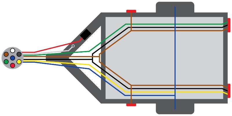
Trailer Wiring Diagram. To connect the electric system of your trailer to the vehicle, you will be using special connector. Above we have describes the main types of trailer wiring diagrams. Below is the generic schematic of how the wiring goes. 4 pin trailer wiring diagram.

Electrical Diagram For A Diy Teardrop Trailer Voyager Travel Trailers
5 days ago - The following trailer wiring diagram(s) and explanations are a cross between an electrical schematic and wiring on a trailer. We recommend these standards because they are pretty universal. That said, for specific situations, there are industrial standards with different connectors and wire ...

Trailer Wiring Diagram Trailers In Denver Co Denver Co Trailer Dealer For Enclosed And Flatbed Utiliity Trailers In Denver At All American Trailers
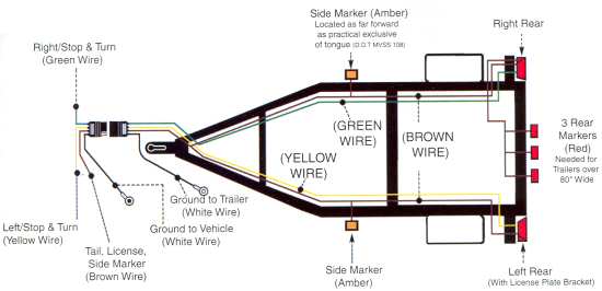
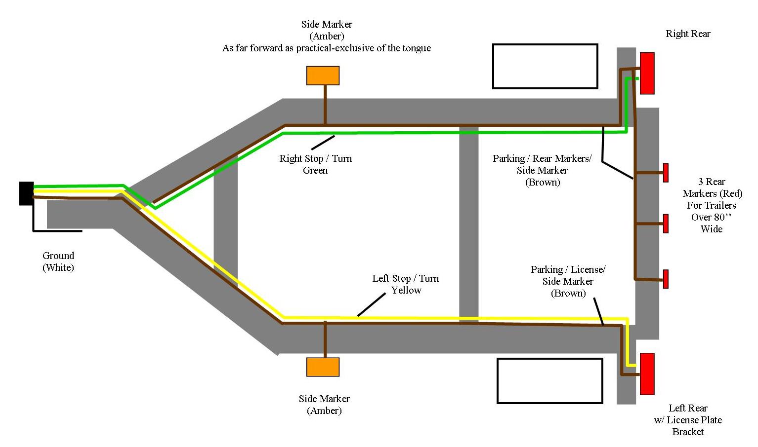
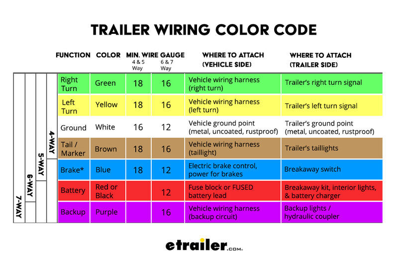
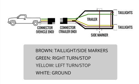
July 5, 2019 - This diagram shows the colors of a basic trailer wiring setup as well as what each wire is supposed to be connected to. ... While it's never a good idea to dive into a wiring project blind, trailer wiring is actually very simple to work on and troubleshoot. For the most part, the wiring harness ...
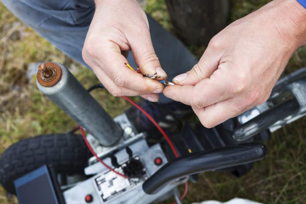
How To Rewire A Trailer In 8 Simple Steps
Trailer side Car side WIRING PLUG DIAGRAM. Title: Wiring Plug Diagram Created Date: 10/22/2009 9:50:14 AM ...
How To Wire Your Trailer Plug To Your Vehicle
Jan 6, 2015 - Follow the progress of our 35' long, 394 sq. ft. custom tiny house and 24'x5' slideout. Photos, videos, timeline, blog, eBooks, Sketchup drawings, and more.

Wiring Diagrams C B Quality Trailer Works Inc
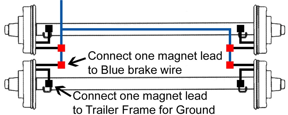
In this 6-pin trailer wiring diagram, as it can be observed, there are two new wire positionings. The blue wire responsible for the hydraulic brakes is now used for electric brakes. The black wire is an indicator for the +12v battery attached to the trailer—the other wires are in the same fashion as the previous trailer diagrams.
Plugs Pj Trailers
Australian Trailer Plug and Socket Wiring Diagrams; Australian Trailer Plug and Socket Wiring Diagrams. 7 Pin Flat The best! All diagrams are as viewed from the Cable Side. 12 Pin Flat This is an extension of the 7 pin flat. The 7 pin flat plug will fit into a 12 pin flat socket and work perfectly.
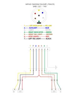
Wiring Diagram Tailgate Trailer Wiring Diagram Tailgate Trailer Pdf Pdf4pro
Wiring Diagram. Trailers are required to have at least running lights, turn signals and brake lights. To provide the power and a hook-up for these, the tow vehicle's wires are tapped into. This is accomplished through either a T-One connector (if available for your vehicle) or through hardwiring.

Pin On Electric Wiring
7 Round Plug Wiring Diagram - Wiring Data Diagram - Trailer Lights Wiring Diagram 7 Pin by Bismillah First, knowing the diagram of cables for trailer will be helpful during troubleshooting. When issues occur using the trailer, motorist might want to understand where the problem place is located.
Trailer Wiring Diagrams Etrailer Com
Trailer Wiring Diagrams Trailer Wiring Connectors Various connectors are available from four to seven pins that allow for the transfer of power for the lighting as well as auxiliary functions such as an electric trailer brake controller, backup lights, or a 12V power supply for a winch or interior trailer lights.
Four Pin Trailer Wiring Install Wiring Diagram Info
Complete with a color coded trailer wiring diagram for each plug type, including a 7 pin trailer wiring diagram, this guide walks through various trailer wiring installation solution, including custom wiring, splice-in wiring and replacement wiring. If your vehicle is not equipped with a working trailer wiring harness, there are a number of different solutions to provide the perfect fit for ...
Trailer Wiring Diagrams Etrailer Com
Trailer Wiring Diagrams 4 Way Systems. 4 way flat molded connectors allow basic hookup for three lighting functions; right turn signal / stop light (green), left turn signal / stop light (yellow), taillight / license / side marker (brown) and a ground (white).
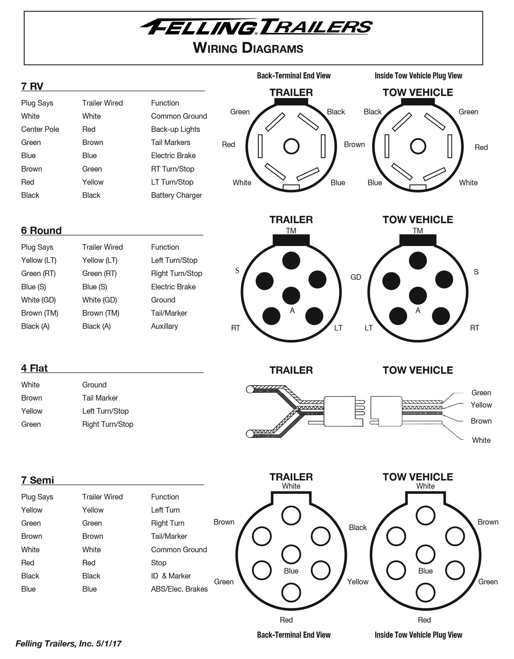
Service Felling Trailers Wiring Diagrams Wheel Toque
6-Pin Trailer Wiring Diagram. White Pin to your ground. Attach WHITE ground wire to vehicle frame. 34 inch by 1 inch 6 way rectangle connectors right turn signal green left turn signal yellow taillight brown ground white. 1 Check all small wires and make sure they are connected to the small fluid control solenoids.

Trailer Wiring Diagram Lights Brakes Routing Wires Connectors
Plug Wiring Diagram Double A Trailers

7 Pin Trailer Plug Wiring Diagram Click Image For More Details Campingtips Trailer Light Wiring Trailer Wiring Diagram Boat Trailer Lights

Trailer Wiring Diagrams Trailer Light Wiring Trailer Wiring Diagram Car Trailer

Trailer Wiring Diagram Tacklereviewer
Trailer Wiring Diagrams 19 Tips Towing Electrical Wiring Installation
Trailer Wiring Diagrams
Trailer Wiring Diagram A Complete Tutorial Edraw
Trailer Wiring Diagrams
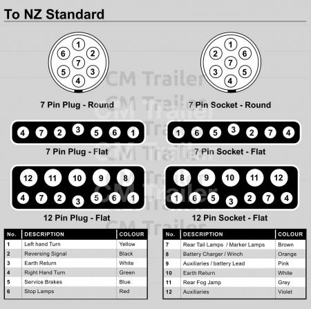
Typical Trailer Wiring Diagram Cm Trailer Parts New Zealand Trailer Parts Accessories Trailer Lights Boat Trailer Parts Trailer Wheels Tires Brake Systems For Trailers
4 Wire Trailer Wire Expert Guidelines On Wiring A Trailer
Trailer Wiring Diagram And Installation Help Towing 101

Airstream 7 Way Wiring Diagram Inland Rv
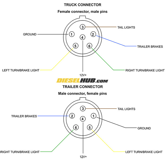
Trailer Connector Pinout Diagrams 4 6 7 Pin Connectors
7 Way Diagram Aj S Truck Trailer Center

140 Trailers Ideas Vintage Camper Vintage Trailers Vintage Travel Trailers

Wiring 13 Pin Trailer Caravan Euro Plugs Uk Trailer Parts
Ifor Williams Trailers Wiring Diagram Sticker Decal Self Adhesive Trailerspares Ie
0 Response to "43 wiring diagram on a trailer"
Post a Comment