45 ul924 relay wiring diagram
The rPP20 consists of a relay, 0-10V dimming control, and a low voltage power supply output to power and wireless switches and sensors. The rPP20 is capable of switching loads up to 20A via a latching relay designed with robust inrush protection from the harsh switching requirements of fluorescent and LED loads. the Emergency wiring leads on the ELCU in series with the emergency lighting load as shown in the wiring diagram. Connect the neutral for the emergency circuit to the Emergency Neutral lead as shown in the wiring diagram. 3. Connect the ELCU to the control device for the area controlled. Connect the
The UL924 Automatic Load Relay (ALCR1277) allows the emergency lighting in a space to be controlled along with the normal lighting while ensuring that the emergency lighting will be forced to full bright upon loss of normal power to the space. Meets NEC Article 700 requirements for emergency lighting. Dual voltage, 120 or 277V operation.
Ul924 relay wiring diagram
UL924 Emergency Lighting Automatic Load Control Relay, 20 Amp SPST, Universal 120-277 Vac, 0-10 Vdc Dimmer Override, Dry Contact Fire Alarm Interface Nine 24 Inc. is a leader in the emergency lighting industry as a developer and manufacturer of emergency lighting load control devices used to control lighting loads connected to a backup generator in the event of a loss of normal power. We strive to provide the best possible service using the highest quality parts. MORE ABOUT US. WIRING DIAGRAM ORDERING INFORMATION ADDITIONAL RESOURCES LUT-ALCR-D Installation Sheet FAQ Sheet Alternative Wiring Sheet Terms & Conditions/Warranty Information 20170816_LUT002_Spec LVS, Inc. 2555 Nicholson Street, San Leandro, CA 94577-4216 Phone: 510-352-9600 1-800-982-4587 Fax: 510-352-6707 www.lvscontrols.com DESIGNATED EMERGENCY LIGHTS ...
Ul924 relay wiring diagram. FORM-C type relay and the UL 924 as a FORM-A type relay. Both transfer devices sense normal power, and upon its loss, cause the relay to connect the emergency power to the lights. Because there are two different power sources for a UL 1008 device, it has to undergo a completely different test program than the UL 924. Two big safety concerns are Wire input #1 or #2 and neutral are connected inter-nally to a sensing circuit. During a power interrup-tion on the sensing input, this circuit causes contact X to drop into a N.C. position and turns on the emergency load(s). Review wiring diagram, on reverse, for details. EPC-1 Flush Mount Ceiling Installation Emergency Relay Wiring Diagram. UL924 Emergency Lighting Relays. Wiring Diagram Relay Insert Panel Right Panel Cover Communication Link Between Command Module and Relay Insert Panel Command Module. Wiring Diagram arrives with numerous easy to stick to Wiring Diagram Guidelines. These instructions will likely be easy to comprehend and use. 2. Wire relay according to wiring diagram. 3.The Wattstopper ELCU emergency lighting control unit is a self-contained device that allows any standard lighting control device to control emergency lighting in conjunction with normal lighting in any area within a building. If power is lost for any reason, including the tripping of a single branch ...
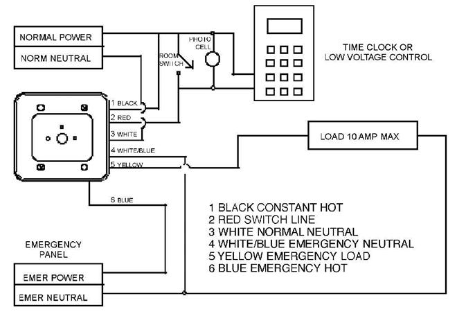
& relay logic regular load b wiring diagram - ecs00-110 room with (1) light fixture wiring diagram - ecs00-110 dual light level switching model: ecs00-110 emergency load emergency hot blue emergency switch leg yellow emergency neutral 5 6 120v 1 black 277v 2 orange normal line hot * white 1 3 20 amp breaker switch leg room switch optional n.o ... UL924 Enclosed 20 AMP Emergency Lighting Control Relay Our enclosed 20 Amp electrically held UL 924 Automatic Load Control Relay is specifically designed for projects requiring control of an emergency lighting along with controlled general lighting in ... Wiring Diagrams. Created Date: UL 924 relay is provided on some units for automatic emergency lighting control. The UL 924 relay automatically tracks with output 1 and can be connected to any of the three ... Wiring Diagrams Sample Wiring Diagram Dual Technology Wall/Corner Occupancy Sensor 20A Receptacle Control RC-6TSB-TS7-* Teacher Station Row 3 Lower Raise All Off Row 1 ... UL924 qualified emergency LED drivers detect the loss of power and switch control to battery power in emergency conditions. The diagram below illustrates the typical EM battery backup system. The detailed wiring diagram below illustrates that the emergency LED driver powers the LED LOAD using the AC LED driver input, in normal power mode, and ...
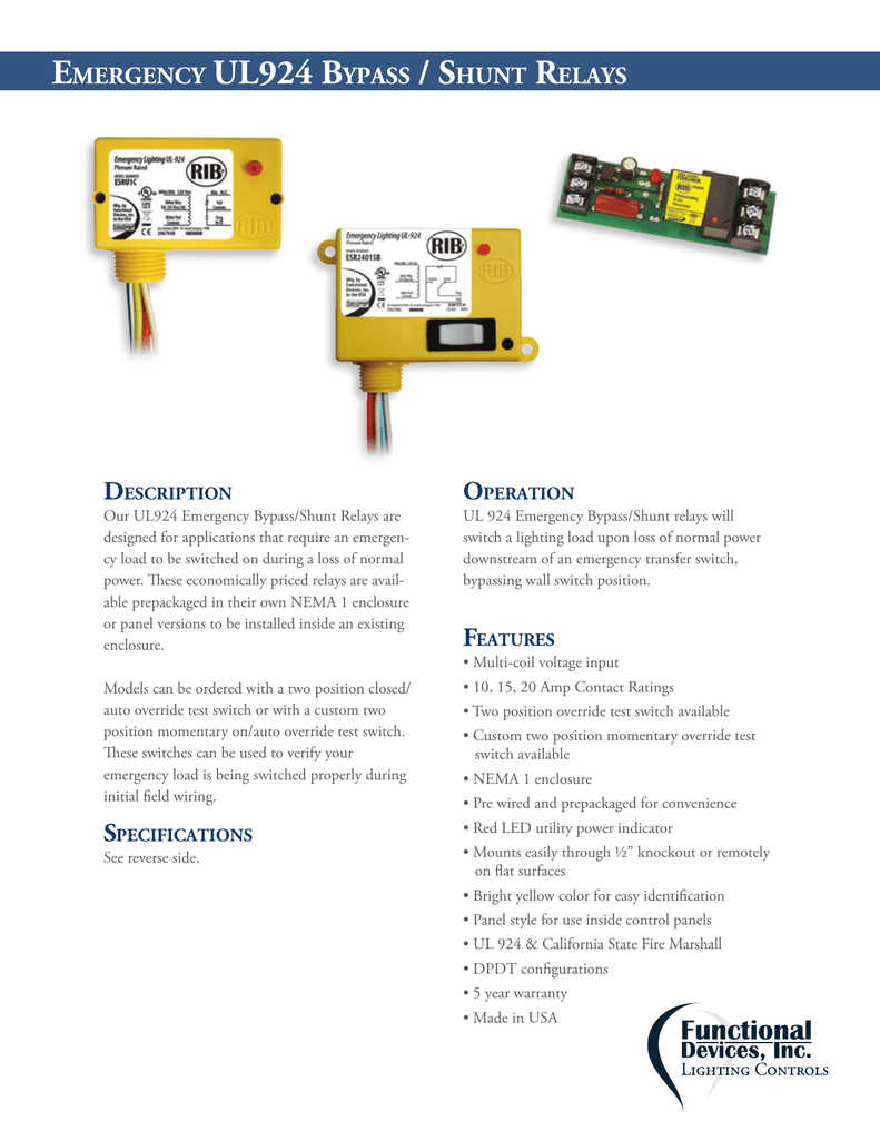
Emergency UL924 Bypass/ Shunt Relay. The Wattstopper ELCU-200 emergency lighting control unit is a self-contained device that allows any standard lighting control device to control emergency lighting in conjunction with normal lighting in any area within a building. If power is lost for any reason, including the tripping of a single branch ... 11 UL924 Bypass, GreenMAX 0-10V, 4-Wire Dimmed Load 12 UL924 Bypass, 0-10V, 4-Wire Sector Relay Dimmed Load 13 UL924 Bypass, Provolt, Auto-ON/OFF, Manual-ON/OFF 14 UL924 Bypass Daylight Harvesting, Provolt Dimming, 2 Zones 15 UL924 Bypass Daylight Harvesting, Dimming, 2 Zones 16 UL924 Bypass, PE300 Load Equal to 0-10V Dimming 17 DRC ... The UL924 XPoint Wireless ER Light Controllers are designed to drive the controlled luminaires to full light output (relay closed, dimming output at maximum trim setting) if there is no line voltage detected on the normal power circuit sensing leads. Enclosed Relay 20 Amp DPDT with 120 Vac Coil Notes: Not rated for use as a UL1008 Transfer Device. UL924 / 20 AMP BYPASS / SHUNT RELAY Not rated for use as a UL1008 Transfer Device Speci˚cations I eri˚cation 1. Turn OFF Normal Power and Transfer Power. 2. Wire relay according to wiring diagram. 3. Energize Transfer Power.
Hubbellcdn Com
UL924 Emergency Lighting Relays. Our UL924 Emergency Lighting Relays can be used for automatic load control or bypass/shunt applications to turn on emergency lighting in the event of the loss of normal utility power. In automatic load control applications, when normal power is present, the ESR relay coil is activated and the emergency panel is ...
Myerseps Com
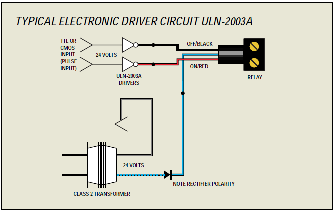
controls using an auxiliary relay contact. The GTD20A includes three dry form C contacts, which allows the user a wide variety of wiring options. For additional applications and information, contact the factory. The GTD20A is suitable for use in indoor and damp locations. Operation The GTD20A senses the loss of normal power and
Avi On Com
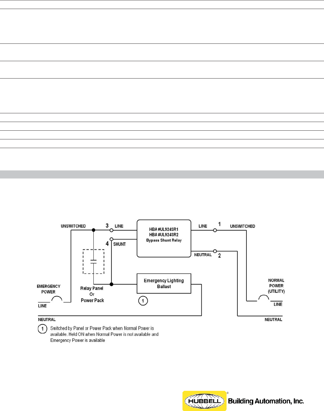
WIRING DIAGRAMS - LX and CX Panels, Power Packs and wiHUBB Smart Packs The Hubbell Building Automation UL 924 Enclosed Bypass Relay with Remote Emergency Control can be connected to various Hubbell Building Automation control systems and devices as indicated in the following wiring diagrams.
Avi On Com
UL924 Automatic Load Control Relays (ALCR) Why is the EPC-D-F (UL924 Listed) being replaced by the EPC-D-F-ATS (UL1008 Listed)? Still have questions? A no-charge 30 minute webinar is available by con-tacting TechSupport@LVSControls.com Several years ago, National Electrical Code (NEC), Article 700 requirements surrounding

Rib Esrn Emergency Lighting Relay Ul924 3961514c For Sale Online Ebay
LightLEEDer Emergency UL924 Lighting Control. The LightLEEDer Emergency UL 924 bypass relay control panel will force relay's ON during a normal power outage. This panel has all the same features and functions as a standard LightLEEDer lighting controller, allowing normal control of relays with emergency bypass during a normal power failure event.
Avi On Com
RRU - UL 924 Remote Relay Unit Overview The Remote Relay Unit (RRU) supports 120 VAC and 277 VAC input voltage configurations. The RRU is designed to force all outputs in the lighting control panel to an emergency scene regardless of the control panel's programmed output status. This
Acuitybrands Com
UL 924 Enclosed Bypass Shunt Relay. Hubbell Building Automation's enclosed 20 Amp electrically held UL 924 Bypass Shunt Relays provide an isolated normally closed contact that can be used as a bypass shunt to power emergency egress lighting directly from the emergency generator source. The coil in these relays is powered by a normal power supply.

Philips Bodine Gtdu Generator Transfer Device For Emergency Lighting
Ul 924 load control relay is not performing a transfer function, but merely a bypass or shunt function. thus it is only required to switch the hot leg of the branch circuit. Some normal-power control devices, however, do not allow shunting, and thus require
Functionaldevices Com
Wiring Diagrams : LSDMXD, LSDMXD-R : pdf R20D Relay and LVS EPC-2 (WD1003) Wiring Diagrams : R20D, EPC-2 : pdf Apprentice 3 Panel (WD0003) Wiring Diagrams : AP3-4, AP3-8, AP3-16, AP3-24, AP3-32 : pdf Wet Location Touch Switch Input Module (WD0401) Wiring Diagrams
Assets Usesi Com
35 Beautiful Ul 924 Relay Wiring Diagram- A control relay is used in the automotive industry to restrict and change the flow of electricity to various electrical parts inside the automobile. They permit a little circuit to rule a sophisticated flow circuit using an electromagnet to manage the flow of electricity inside the circuit.
Functionaldevices Com
Hubbell Control Solutions enclosed bypass Shunt Relays are typically used to bypass a normal control such as a switch, dimmer, or panel mounted relay when used on an emergency circuit. The normally closed relay in the UL924SR1/UL924SR2 connects to the line and load side of the control device. When normal power is lost, the control is bypassed by the normally closed relay and full power is ...
Emergency Ul924 Bypass Shunt Relays
WIRING DIAGRAM ORDERING INFORMATION ADDITIONAL RESOURCES LUT-ALCR-D Installation Sheet FAQ Sheet Alternative Wiring Sheet Terms & Conditions/Warranty Information 20170816_LUT002_Spec LVS, Inc. 2555 Nicholson Street, San Leandro, CA 94577-4216 Phone: 510-352-9600 1-800-982-4587 Fax: 510-352-6707 www.lvscontrols.com DESIGNATED EMERGENCY LIGHTS ...

Acuity Controls High Bay Networked Lighting Solutions Ppt Download
Nine 24 Inc. is a leader in the emergency lighting industry as a developer and manufacturer of emergency lighting load control devices used to control lighting loads connected to a backup generator in the event of a loss of normal power. We strive to provide the best possible service using the highest quality parts. MORE ABOUT US.

35 Beautiful Ul 924 Relay Wiring Diagram Generator House Diagram Electrical Diagram
UL924 Emergency Lighting Automatic Load Control Relay, 20 Amp SPST, Universal 120-277 Vac, 0-10 Vdc Dimmer Override, Dry Contact Fire Alarm Interface
Ul 924 Sr Cut Sheet
Adding Lighting Control To Emergency Circuits Federated Controls
Myerseps Com

Ul924sr 1 2 Series Install Guide Datasheet By Thomas Research Products Digi Key Electronics
Ge Lighting Control System With 24 Emergency Ul924 Rated Relays A 277v Contactor Coil And An 8 Group Input Module In A 48 Capacity Interior
Assets Kele Com
Cooperlighting Com
Alpscontrols Com
Acuitybrands Com

Understanding Control Of Emergency Lighting Circuits Iaei Magazine
Assurancelighting Com

Lightleeder Emergency Ul924 Lighting Control Intelligent Lighting Controls Ilc

Philips Bodine Gtd Generator Transfer Device For Emergency Lighting

Adding Lighting Control To Emergency Circuits Federated Controls
Cooperlighting Com
Avi On Com
Functionaldevices Com
Leducation Org
Functionaldevices Com
Acuitybrands Com
Cooperlighting Com

Understanding Control Of Emergency Lighting Circuits Iaei Magazine
Assets Kele Com
Evenlite Com

Esr2402d Specifications Initial Wiring Verification Field Manualzz
Rexel Cdn Com
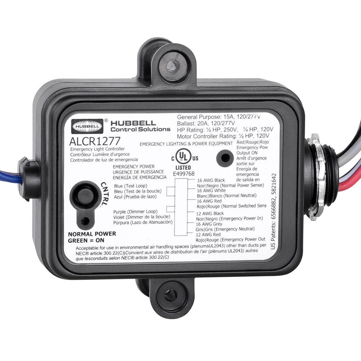
Ul924 Automatic Load Relay Hubbell Control Solutions

Esrb Alpscontrols Com
Ilc Usa Com
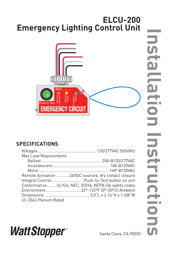
Elcu 200 Emergency Lighting Control Unit

Functional Devices Inc Rib Rib2401b 18 98 Enclosed Pre Wired Relay 20a 277vac Spdt Application Power Zoro Com
0 Response to "45 ul924 relay wiring diagram"
Post a Comment